Wiki
Clone wikiFRA4PicoScope / Plot Gallery
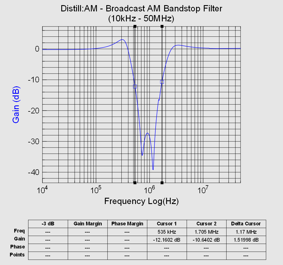
- "Distill: AM" Stopband Filter with AM band marked (535 kHz to 1705 kHz)
Equipment & Settings: PicoScope Model 6242E, 12 bits, 1.0 Vpp, 50 Ohm DC Coupling, Noise Reject Mode, 1 Hz bandwidth, 312.5 MS/s, 100 steps/decade
Notes: Noticeable peaking near transition bands that doesn't show up in the published datasheet. Maybe the one I received is not tuned well?
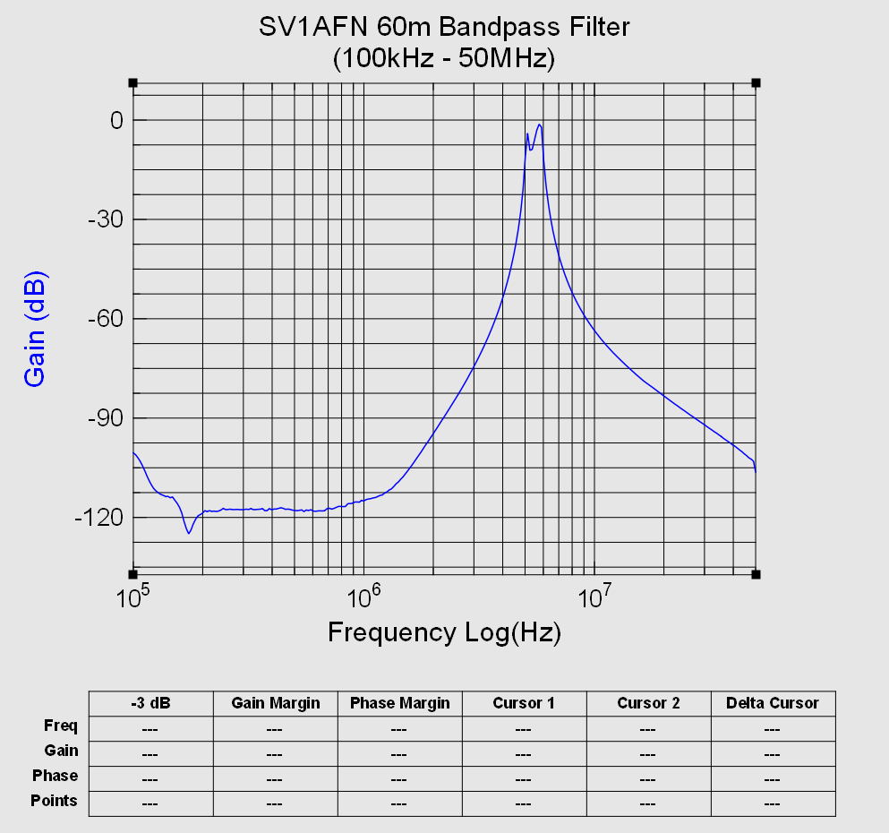
- SV1AFN 60m Bandpass Filter
Equipment & Settings: PicoScope Model 6424E, 12 bits, 1.0 Vpp, 50 Ohm DC Coupling, Noise Reject Mode, 1 Hz bandwidth, 625 MS/s, 100 steps/decade
Notes: Demonstrates the very large dynamic range (-120 dB) achieved by narrow bandwidth and high processing gain afforded by the scope's very deep buffer (1Gs / channel in this mode). The output would be 1 uVpp in this range, which is well beyond the scope's 5 uV resolution (ignoring ENOB). With Gaussian noise present, the very large processing gain (~625 million samples) is able to achieve higher resolution with minimal noise in the gain output.
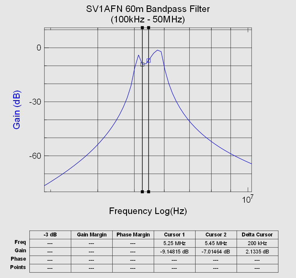
Cursors on 60m band (5.25 to 5.45 MHz):
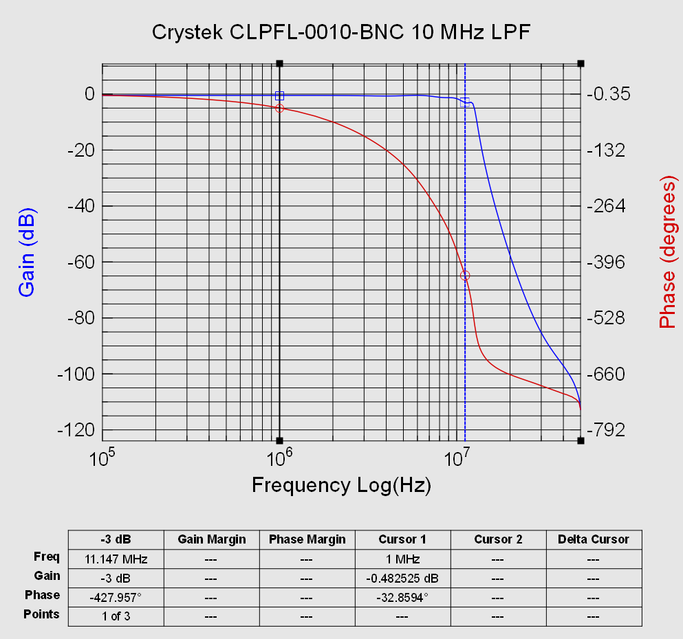
- Crystek CLPFL-0010-BNC 10 MHz Lowpass Filter
Equipment & Settings: PicoScope Model 6424E, 12 bits, 4.0 Vpp, 50 Ohm DC Coupling, Noise Reject Mode, 1.2 Hz bandwidth, 1.25 GS/s, 10 steps/decade from 100 kHz to 2 MHz, 100 steps/decade from 2 MHz to 50 MHz
Notes: Demonstrates the very large dynamic range (-110 dB) achieved by narrow bandwidth and high processing gain afforded by the scope's very deep buffer. Plot also shows phase unwrapping of the 9th Order Chebyshev Response. Three -3dB points are identified due to ripple in the response. The marker is on the lowest frequency of the three. Cursor 1 is placed to show insertion loss.
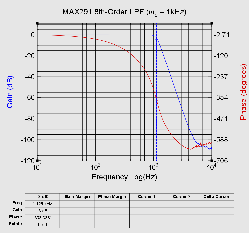
- MAX291 8th-Order Lowpass Switched-Capacitor Filter
Equipment & Settings: PicoScope Model 5444A, 15 bits, 4.0 Vpp, AC Coupling, Noise Reject Mode, 1.0 Hz bandwidth, 62.5 MS/s, 10 steps/decade from 10 Hz to 700 Hz, 100 steps/decade from 700 Hz to 10 kHz
Notes: Passband and Transition band are very flat, as expected for Butterworth response. Corner frequency is within the 20% error expected from a random 300 pF ceramic disc capacitor pulled from a bag. The gain/phase noise at frequencies closer to 10 kHz may be caused by noise from the internal 100 kHz clock.
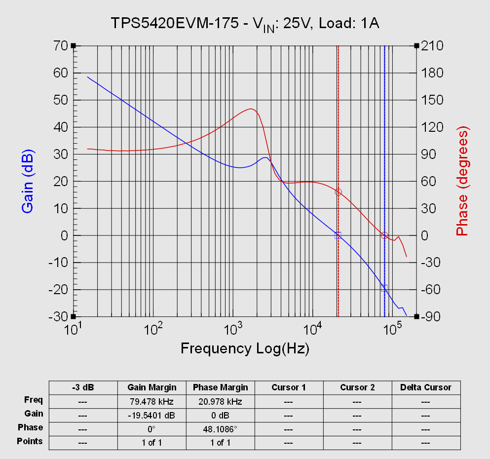
- TI TPS5420EVM-175 with 50 Ohm injection resistor:
Equipment & Settings: PicoScope Model 5444A, 15 bits, Custom Plan (as seen on main Wiki page), AC Coupling, Noise Reject Mode, 1.0 Hz bandwidth, 62.5 MS/s. Jensen ISO-MAX VB-1BB transformer to inject loop disturbance.
Notes: The Phase Margin is not quite as high as reported in the EVM User Guide (55 degrees). I assume it's just due to part-to-part variation. The little peaks past 100 kHz are noise from the E3616A input power supply. Earlier plots with a lead acid battery input did not have these. For SMPS stability measurements, it's best to have the cleanest input possible.
Updated